Studio801 Carousel Project

I offer My thanks to Jon King for his inspration. The Jon King (ca.1980) Carousel model was the start of this project.


1-18-2019
*Hershell-Spillman, 1925*

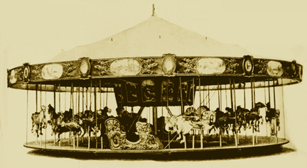
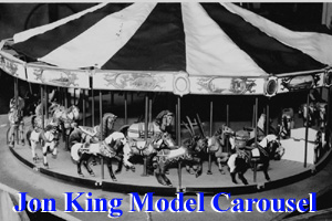
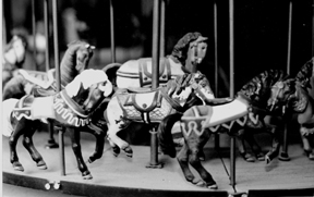
This image was taken for a 1925 Hershell-Spillman catalog of a 32 horse three abreast carousel. It was located on page 213 in the book,"Painted Ponies," (by Mann, Shank & Stevens, 1987.)

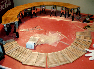
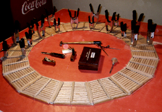
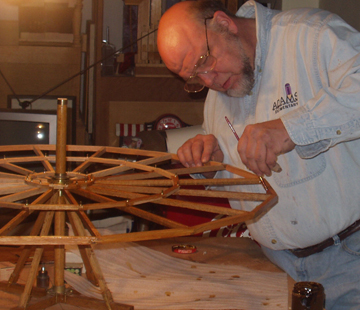
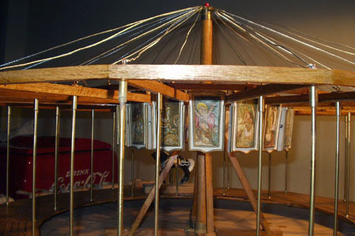
The construction of the Studio Carousel was inspired in 1999 after a three foot diameter scale model was offered. The carousel offered was won at a local auction and was a source of much frustration to its owner. The only "makers marks" found on this carousel were located on the belly of the horses. They were all marked "Jon King ca.1980."

 
The "Jon King" version of the Hershell-Spillman was a good looking model and was very detailed. Its problem however was that it was constructed with many important structural parts made of some type of brittle plastic. The effects of plastic failure can be seen in the image of the "King" model, (right). Notice the rounding boards and deck board part misalignment. No matter how hard the previous owner tried, he could not keep the carousel from falling apart anytime it was touched.
When the carousel was brought to the Studio it was studied and drawn as it was taken apart. These notes & drawings can be seen in this posting. The plastic parts that came with the carousel were used as models in the construction of a new "studio" model. Every wood part of the new "Studio Carousel" has been made of very stable quarter-sawn oak. To hold all of this oak together there has been many pieces of hardware parts made of machined and silver-soldered white brass.
These materials have been found to be much more stable and should prove to be more durable than plastic. (The exception to this, thus far in construction, has been the strands of woven steel picture wire, that is being shown installed as sweep support cables.)
Center Pole and Hardware
The first parts built for the "Studio Carousel" were the wooden center pole and the base "X" frame. In order to keep the pole upright and stable a set of four diagonal braces were made.
 
Assembly hardware need for this section included: a brass sweep bearing or support, the upper wheel spoke frame bearing and horse crank shaft and drive gear. The final part made was the main bearing at the top of the center pole that gives support to the sweeps rods and cables

Drive Support Frame 
 
The photo to the left shows the Carousel Drive frame. It is likewise made of brass that has been silver soldered together. It is made to be mounted across 2 of the flat Center "X" frame arms right near upright cross bracing. This part has a shaft that rotates at its center where small gear is mounted at the top that will be connect to a large Ring drive gear.This gear will be mounted right inside of the innner frame skirt boards. This ring gear rotate the carousel. The inside ring gear will likely be condtructed of silversoldered ladder chain
 
Deck Boards

The 16 platform sections were built using a total of 344 pieces of white oak. To make these sections uniform, a jig was built on a board of 3/4" plywood. To assemble the jig, tiny finishing nails were hammered in place and the nail heads were cut off. These nails became board spacers. Thirteen small planks of oak were laid between the nails across the jig board and six thicker sticks were glued into place then clamped. When dried, these floor sections were removed and trimmed to shape. When all the sections were assembles, they were shellac and laid in a circle and matched to the 8 upper wheel sweep sections. Finely the 16 sections were glued and clamped into a wheel, (one half at a time.)

 
Upper Wheel sweeps
There are 16 spokes in the upper sweeps forming a wheel that fit into compartments of the lower center bearing. This image shows the artist applying shellac to control moisture in the wood parts this wheel. The upper spokes are the main grid that the entire carousel is built upon. There are 2 hooks on each spoke for cables that will be used to support the wheel as well as the weight the rest of the carousel. These cables are strung to the top of the carousels center pole through holes in the upper bearing. This wheel is also the support for eight, two throw, crankshafts that will be installed to make the horses go up and down.
The Photo above links you to a You Tube video of the Carousel
Cables and Drop Rods

As you can see in this image of the upper wheel of the "Jon King" carousel (left), there is a lot of confusion seen from wires cables (in this case nylon string) and crankshaft parts. One of the intention in the construction of the studio Carousel was to clean up the look of the upper wheel.

It is important to detail all hardware to be designed and built functional and attractive. The hooks are made of three silver soldered brass pieces: a loop, bolt, and face plate. For function, the hooks are held in place on

t
the wheel spokes using 10-32 brass bolts set through the spokes. To makehese hooks more attractive these cable support hooks are detailed with two # 0-80 bolts set in each face plate.
 
32 Carved Horses

The horses found on the "Jon King" carousel, like other other parts found on this model, were made of plastic," an epoxy that looks a lot like auto body putty." And like many of the other plastic parts used in the assembly of this model were un-stable. You simply had to look strong at a horse for things to start falling off of them.

Early in the planning process of the "Studio Carousel," it was decided to carve a set of new horses. To that end, the Jon King Horses were all drawn in the notes to plan

for carving. As can be seen in the notes below, Bass Wood was cut into strips, 1-1/2" x 1-3/8" x 12" long to start the forming of new horses.
These boards were machined in a shaper to round off both of the top edges. This left a center raised area that would later be carved into the saddles. Next the both of the lower edges of the strip were relieved, in four cuts of the table saw. This made the areas where legs would later be glued in place. The strips that were removed from the bottom edges were saved and cut later using them as fill blocks between the legs. Before any gluing of parts however the machined wood had to be cut into 3-3/8" blocks. Each block was drilled for the carousel pole and slanted cut was made for later instillation of the head.
       
Inside Skirt Paintings
16 small pictures were made for the Jon King model and they were located on the inside carousel skirt. This skirt coverers the horse crankshafts

and drive gears. These paintings were made of paper and were lithographic prints. They were cut out glued to canvas and were detail painted to make them look like real paintings. These finished images were placed into "wood based" plastic covered frames and glued in place.

For the Studio version of these parts, the paintings are being copied and reproduces using in Acrylic

paint on Canvas. As to the frames, they will be built in red oak.
 
Light Bars
Each of the 16 upper frame spokes have been fitted with a light bar. This assembly of six, quarter inch diameter, screw-in type, model railroad train light bulbs, were built to simplify the electric of lighting the carousel. In the finished carousel there will be a total of 96 light bulbs. Each of these bulbs requires a positive and a negative wire to operate. This fact alone translates into a serious mass of wiring and a logistical nightmare. (Look above at the image of the Jon King carousel found in "Cables and)
Supports Rods" to see the many wires used to light this carousel.) Another methods of adding light had to be used. One of the note book pages shows the light bar design that was used.
 
 
To make each of these light bars, a 6 inch section of 1/4 by 14 inch square brass tubing was used as a foundation. This brass is first drilled to fit four light sockets along its length. Then both ends of the bars were filed, and sockets were installed there too. With both the bar being brass as well as having brass light sockets both could be soft soldered easily and filed smooth.

As to the electrical logistics, with the sockets being soldered into the brass bar it-self, the bar allowed for a simple method of attaching the grounding wire to all six bulbs. To finish the electrifying, A positive wire was soldered flat to the center pin of each socket, This bridging continued socket by socket to the other end of the bar. With all of the sockets linked together, a power wire was hooked to an end socket and string of lights was tested. See how these light bars made for a cleaner light instillation.

NOTE: The tool made to install and change bulbs.
 
Click on the "Orchestrion" Icon to link to view This Studio 801 Project. Click on the "Resume" Icon to link to Gary Stevenson's professional Resume and to many other Studio 801 items   Click on the "Home Page" Icon to return to the "Studio801" home page